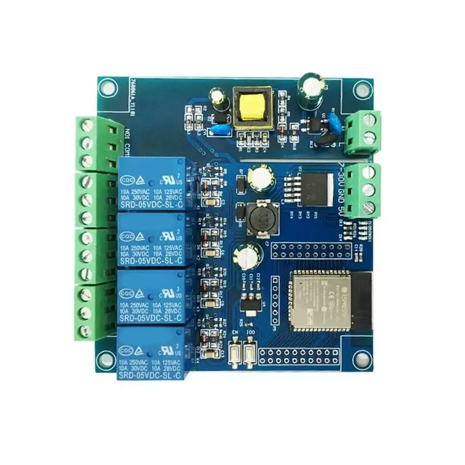
ESP32 LC-Relay 4R-A2
Beschreibung:
Ein fertiger ESP32 mit 4 Galvanisch getrennten relais.
Komplett fertig.
https://www.amazon.de/dp/B0D3WJMCC3?ref=fed_asin_title
Gehäuse 3D Druck
| Name | Bild | Link |
|
Box |
|
4Channel_ESP32 - BOX.stl |
|
Deckel |
|
4Channel_ESP32 - LID.stl |


Quelle: https://www.printables.com/model/1084217-esp32-4-channel-relais-modul-case/files
PIN Belegung:
Programming header pinout
| Pin | Comment |
|---|---|
| 5V | Do not use 5V for programming |
| TX | Exposed on board 3.3V level! |
| RX | Exposed on board 3.3V level! |
| GND | |
| GND | |
| GPIO0 | 3.3V level! (Connected to a push button for programing) |
Internal pinout
| Pin | Function |
|---|---|
| GPIO23 | Status LED |
| GPIO32 | Relay #1 |
| GPIO33 | Relay #2 |
| GPIO25 | Relay #3 |
| GPIO26 | Relay #4 |
Flashen:
Siehe Programmer : AZ-Delivery Programmer
GND und GPIO0 mit einem Jumper überbrücken
5V vom Prgrammer an V5
RX vom Programmer an RX
TX vom Programmer TX
ESP32-Home Code Beispiel für 4 Relais als Taster
output:
  - platform: gpio
    pin: GPIO23
    id: led
  - platform: gpio
    pin: GPIO32
    id: relay_pin_1
  - platform: gpio
    pin: GPIO33
    id: relay_pin_2
  - platform: gpio
    pin: GPIO25
    id: relay_pin_3
  - platform: gpio
    pin: GPIO26
    id: relay_pin_4


# Define the switches based on the relay pins
switch:
  - platform: output
    id: relay_1
    name: "Relay 1"
    output: relay_pin_1
  - platform: output
    id: relay_2
    name: "Relay 2"
    output: relay_pin_2
  - platform: output
    id: relay_3
    name: "Relay 3"
    output: relay_pin_3
  - platform: output
    id: relay_4
    name: "Relay 4"
    output: relay_pin_4


interval:
  - interval: 1000ms
    then:
      - output.turn_on: led
      - delay: 500ms
      - output.turn_off: led